I Made A Blinkey Keychain
Getting To Blinky
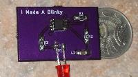
May, 2017: Just, don't look too closely at the soldering… that was my first try assembling with SMD parts, and I was using a cheap $20 soldering iron (the kind you plug directly into the wall, and worry about when your fingers — well and truly on the hand grip mind you — are getting a little uncomfortably warm), and with no magnification, extra flux, etc. All things considered, I think it went pretty well. Apart from the mistake in the tutorial (and my mistake for copying it over despite suspecting I'd spotted a mistake), it all went together just fine. Though yes, that is a through-hole LED soldered to the SMD pads, because I'd forgotten to order the most important part of all — the LED's!
Second Run
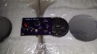
Aug, 2017: Not content with the hackish stylings of the (7)555 with one leg lifted in the air, and being slightly more versed in KiCad now than I had been, a re-spin of the board was in order. Other benefits to doing a second version; a chance to add a push button (with associated practice designing a custom footprint), tried out adding a bit of custom silk-screen art (my site mascot), actual SMD LEDs this time, the soldering is a little better (mostly having to do with access to a better soldering iron at the local hacker space), and discovered the wonders of a component tester — because as much as those LEDs are supposed to have a polarity indicator, I couldn't find it.
Freedom from the desk!
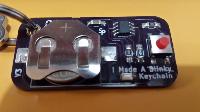
2018: The Blinky was great. Feeling like some blinking, it's sitting there on my desk, just reach out and press the button… instant blinky gratification… but there was a problem. Much of the time when that urge for blinkage strikes, you're not sitting at your desk. You're out, waiting for an appointment, fine dining at McDonands, attending an important seminar, etc. So, version three turned it into a keychain!!! Now, I have my blinky wherever and whenever I need it! On the back, is my name, phone number, and a QR-code (which unfortunately won't scan — I'd had my doubts, and only one way to find out) that links to my site here. That way, if my blinky gets lost (also, the keys attached to it), it can hopefully find it's way home again.
The Future
Well, what to do next… more blinking of course! Some time in the [hopefully] not too distant future, I plan to step it up from the current (7)555 circuit, to perhaps a little 8-pin ATtiny ųC, stepping the simple red LED up to an RGB LED, and give it a few simple little patterns. Probably try to keep the form as similar as possible, though it might do with a second button…
Desk Clock (ish)
The Second Prototype
Nov, 2018: Unfortunately, I never took any pictures of my Desk Clock, in any of it's forms to date. The only picture I have, is way up in the top right corner of a photo of my desk, and it's grainy as heck. This was the second version of my desk clock, with the temperature sensor and display on a breadboard — and a horrible nest of loose wires connecting them. Next I added an RTC module, and then a pair of push buttons for the menu, which at this point hadn't actually been fully reimplemented, only basic time and temperature (though the full featured menu was planned out).
The Desk Clock Lives!
Aug, 2017: So the board and parts arrived, and it's a success, mostly… A clock without a display, but it has ethernet, an LED, light sensor, two temperature sensors, and a pair of push buttons.
May, 2018 Now it's been connected to my Home Automation setup for a couple months, and I've finally actually connected the second (external) temperature sensor. So all that data is available in automations, and the Hass.io interface, which does indeed do pretty graphs. Automation wise, the light sensor is used to turn my lamp off during the day, and I'm using one of the push buttons to put the system in and out of sleep mode
(also turns off the light, but also the RGB LED Strip running it's light patterns).
The Future
It's out of memory — as much as I was afraid of — haven't decided what to do about that yet. Version 2.1 of the board is now mostly just waiting for me to decide on a display to use; fixed up the LED and other minor niggles, moved a few tracks around, improved the ground fill a little, and swapped the temperature sensor with the LDR to give it more distance from the warm spots on the EtherTen (mostly the Ethernet chip).
LED Strip — For the Colours
Beginnings
A year or two ago, I purchased a 1m strip with 60 APA102 RGB LED's. At the time, my plan was to experiment with them, and then hopefully purchase a longer strip to attach to the house for event lighting effects such as Christmas. Also planned, was a less interesting analog white strip to run along the entry path, probably another RGB strip for hallway lighting, and so forth.
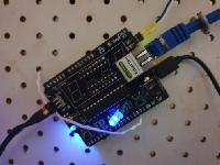
Then my life changed. And then it changed again. Finally in 2018, I was inspired to put them to use, and with the help of an Arduino (EtherTen, specifically, an Arduino Uno clone with integrated Ethernet support), they are now finally situated on my desk below my monitors, running through a sequence of patterns.
I'm still thinking of getting some more for the hallway — albeit a different hallway. Planning on going with basic analog in white or CCT… only ever passing through, however, so a nice quick fade in, slower fade out, nothing particularly fancy at all.
Arduino Expanded
They outgrew the Uno. Mostly the Ethernet support, with that one library and it's buffers taking up a significant slice of the little ųC's limited resources, plus the MQTT and minimal web server it now supported (Web was first, then factored out the command handling so it would also function over MQTT). What space was left, barely fit the patterns, and I still wanted to add colour palletes for themes.
I'd added my own patterns, but the existing ones didn't get by unscathed, either — the indicators I wanted to add, required dynamically reducing the spread of the pattern to allow some pixels at either end to be taken up for indicators. The present form, works by specifying the start and end extent of the pattern, and then allowing writing a run of colour to a set of pixels. So by reserving a few pixels at the end, and then writing your chosen colour, you get an indicator. A little Python scripting later, and it's even a nice neat packaged command.
So the Uno was replaced with a Mega (EtherMega, an Arduino Mega clone with integrated Ethernet). Much more space to grow… plenty for those colour palettes I wanted to add. And that is how it remains today.
The Future
Presently, a breadboard is bridging the Arduino to the LED Strip. I've drawn up a small PCB to take it's place, both to look better, and be more reliable. I had wanted to also use the onboard SD Card port for storing additional colour palettes, but these boards have a small issue with their Ethernet chipset that messes up that idea.
I had considered patterns by SD Card also, but, that would require some kind of interpreter, and the Mega's already pretty busy running the LED strip at a nice high frame rate for smooth colour fades.
While helping someone else out with a similar project, I realised I could fit more built-in patterns and palettes, if I just offloaded all the palettes into an app. It could even hold them all in Flash as a pre-compressed JSON file, allowing said app to retrieve the file, and reflect the chosen palette back to it. It is after all, intentionally being remotely controlled.
But in the time this has been running in it's present configuration, it's been fine just as it is. So I think until I actually have something useful to add, I'll be leaving it just as it is.
